
Choosing an audio amplifier IC for a new product is both an engineering and a supply-chain decision. Class D designs often offer high efficiency and lower heat at meaningful output power, while linear designs such as Class AB can simplify the signal path and avoid a high-frequency switching output stage. Neither architecture is universally better.
The right choice depends on the required output power, speaker impedance, supply voltage, THD+N test condition, acoustic goals, thermal limits, EMI requirements, package, lifecycle status, and sourcing plan. This guide explains how to compare the architectures and prepare a specification that a supplier can quote and verify.
Key Takeaways
- Compare output power with the same load, supply, frequency, bandwidth, and THD+N condition.
- Class D is often a strong fit for portable or space-constrained products, but switching noise, layout, filtering, and EMI validation remain important.
- Class AB can be useful when a simpler linear output stage or low switching activity is preferred, but its heat dissipation must be designed at the actual load.
- A package does not determine audio quality. Check the device data sheet, exposed-pad requirements, board layout, assembly process, and thermal resistance together.
- A sourcing request should identify the exact MPN, revision, lifecycle status, approved alternatives, traceability documents, compliance requirements, and sample-validation plan.
What “Analog” Means in This Comparison
“Analog amplifier” is an umbrella term rather than one single topology. It can include Class A, Class AB, Class G, and Class H output stages.
- Class A keeps the output devices conducting continuously. It can offer a simple operating concept, but idle and load-related dissipation can be high.
- Class AB shares conduction between output devices and is a common linear approach for balancing distortion, efficiency, and complexity.
- Class G and Class H use changing or tracking supply rails to reduce wasted voltage in some operating conditions. Their behavior depends on the specific IC implementation.
Class D uses a switching output stage. The amplifier controls the average output through high-frequency switching and then relies on the output network and speaker load to reconstruct the audio signal. The exact control method, switching frequency, feedback arrangement, filter requirement, and protection features vary by device. Texas Instruments’ Class-D amplifier selection guide is a useful manufacturer example of the parameters that must be evaluated together.
For a fair comparison, define the scope before searching for parts. A “Class D vs analog” comparison should state whether it means Class D vs Class AB, Class D vs all linear classes, or a comparison between specific ICs.
Class D vs Class AB and Other Linear Amplifier ICs
| Decision factor | Class D | Linear classes such as Class AB |
|---|---|---|
| Output-stage behavior | High-frequency switching | Continuous or partly continuous linear operation |
| Efficiency | Often higher at medium or high output power | More power can become heat, especially near demanding loads |
| Thermal design | Switching and conduction losses still require a valid heat path | Dissipation from the output stage can dominate thermal design |
| EMI considerations | Layout, switching edges, return paths, and filtering need attention | No switching output stage, although the complete product can still create noise |
| External components | May require an output filter or specific layout; depends on the IC | May require bias, feedback, coupling, or thermal-support components |
| Low-power behavior | Check idle and standby losses, not only full-power efficiency | Check quiescent current and heat during idle operation |
| Typical fit | Battery products, compact speakers, multi-channel or space-constrained designs | Designs prioritizing a linear path, simple switching behavior, or particular acoustic requirements |
| Procurement risk | Confirm filter, package, layout, and approved operating conditions | Confirm heat dissipation, package limits, and supply availability |
These are design tendencies, not guarantees. The device data sheet and application documentation must take priority over a generic architecture label.
Metrics to Compare Before Selecting a Part
Output Power With Test Conditions
Never compare output power as a standalone number. Record the following for every candidate:
- Supply voltage and whether the output is BTL or single-ended
- Speaker load impedance
- Output power per channel and number of channels
- Test frequency
- THD or THD+N at the stated power
- Audio bandwidth and measurement weighting
- Clipping or protection conditions
For a resistive approximation, output power can be screened with P = Vrms² / R. Real audio IC behavior also depends on output swing, current limit, distortion, switching losses, and the speaker’s impedance curve. Use the manufacturer’s rated conditions for the final comparison.
THD+N, SNR, and Noise
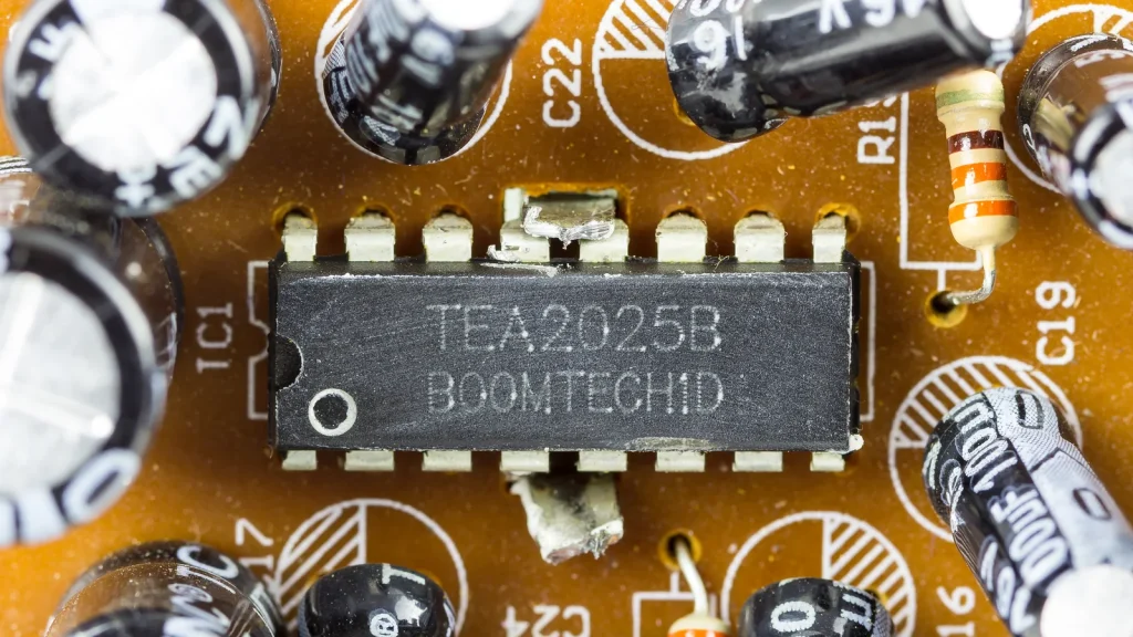
A lower THD+N figure is useful only when the test conditions match. Check gain, load, supply, frequency, bandwidth, and output level. SNR also depends on the reference level, weighting, and measurement bandwidth.
For Class D, include switching residue and output-filter behavior in the measurement plan. TI’s EMI application report illustrates why layout and emissions should be assessed as part of the system, rather than inferred from the amplifier class alone. For linear designs, check crossover behavior, clipping recovery, and noise from the input and feedback stages.
Supply, Input, and Output Configuration
Confirm:
- Operating supply range and absolute maximum ratings
- Analog, digital, differential, or single-ended input
- BTL, single-ended, headphone, or line-level output
- Required gain and input common-mode range
- Shutdown, mute, standby, and wake-up behavior
- Output filter requirements and speaker-connection limits
A part that meets a headline power target may still be unsuitable if its input interface, gain, or output configuration does not match the system.
Efficiency, Quiescent Current, and Standby Current
For battery products, compare efficiency at the actual listening levels rather than only at maximum output. Record normal idle current separately from shutdown or standby current.
For any efficiency figure, note the supply voltage, load, output power, frequency, and whether external DC-DC conversion is included. Do not mix amplifier efficiency with the efficiency of a separate boost or buck converter.
Protection and Diagnostics
Review the actual behavior of:
- Over-temperature shutdown
- Short-circuit or output-current protection
- Under-voltage lockout
- Over-voltage protection, if provided
- DC-fault detection
- Pop-and-click suppression
- Fault pins or status reporting
Protection thresholds, timing, and recovery behavior are device-specific. Treat them as requirements to verify, not as proof that a product is safe under every fault condition.
Thermal Design and Package Selection
Thermal design starts with loss, not the advertised audio output. A first-pass estimate can use:
P_loss = P_in – P_out
and, where the data sheet permits a screening calculation:
Tj ≈ Ta + P_loss × θJA
These equations are not a substitute for the manufacturer’s thermal guidance. θJA depends on the test board, copper area, vias, airflow, board orientation, and measurement method. TI’s thermal-characteristics application report shows why package thermal values must be read with their specified test-board conditions. Use the selected device’s data sheet and application note for the final design.
When evaluating a package, confirm:
- Whether an exposed pad must be soldered to a defined copper area
- The recommended land pattern and via design
- Maximum package and junction-temperature limits
- Assembly capability, inspection method, and rework constraints
- Clearance, creepage, mechanical height, and acoustic enclosure limits
- Whether the package and pinout are compatible with approved alternatives
DIP, SOIC, QFN, QFP, BGA, and power packages should not be treated as interchangeable examples. Package choice affects assembly and thermal behavior, but it does not by itself determine THD, SNR, or sound quality.
Application-Based Shortlisting
Portable and Battery-Powered Speakers
A Class D IC with shutdown control and suitable efficiency may be a practical starting point for a portable speaker. Confirm the battery range, boost-converter interaction, speaker impedance, idle current, acoustic output target, and EMI limits.
Do not assume that a single 5 V rail can deliver any desired output power. Use the required RMS voltage, load impedance, output topology, current limit, and thermal conditions to check feasibility. If a boosted rail is needed, include the converter’s losses, cost, noise, and sourcing risk in the system BOM.
Low-Switching or Simple Linear Designs
A Class AB IC can be considered when the design benefits from a linear output stage or when switching behavior is difficult to validate in the product. The trade-off is greater heat at higher output levels. Check the actual dissipation, enclosure temperature, heatsink or copper area, and protection behavior.
Multi-Rail or Higher Dynamic-Range Designs
Class G or Class H may be relevant when changing supply rails can reduce linear-stage losses. These architectures add control and rail-management considerations, so confirm the rail transitions, external supply requirements, noise behavior, and available manufacturer guidance.
Audio Amplifier IC Sourcing Checklist
Before asking a supplier for options, prepare a structured requirement:
- Electrical target: supply range, output topology, channel count, load impedance, output power, THD+N, gain, bandwidth, and input interface.
- System conditions: battery or mains supply, ambient temperature, enclosure, duty cycle, EMI/EMC limits, and required protection behavior.
- Package and assembly: package outline, exposed-pad requirements, PCB capability, reflow or through-hole process, inspection, and rework constraints.
- Lifecycle: active, NRND, EOL, or obsolete status; last-time-buy information; PCN/PDN history; and approved replacement rules.
- Traceability: exact MPN, manufacturer, date code, lot information, packaging, certificate of conformance, and any required authenticity checks.
- Compliance: RoHS, REACH, conflict-minerals, export, automotive, medical, or other requirements only where they apply to the product and market.
- Commercial terms: sample quantity, MOQ, lead time, price basis, currency, delivery location, and validity period.
- Validation plan: sample inspection, electrical test conditions, listening or system test, thermal test, and change-control process.
For a multi-line BOM, link this article to the audio amplifier IC category, BOM kitting service, and Quality Assurance pages. For a technical review, direct the reader to the Technical Advisor page before requesting a quote through the Contact page.
RFQ Information to Send a Supplier
| Requirement | Example information to provide |
|---|---|
| Target application | Portable speaker, display, industrial product, or other confirmed use case |
| Electrical target | Supply, load, channels, output power, THD+N, gain, and input type |
| Mechanical target | Package, board limits, exposed pad, height, and assembly process |
| Supply requirement | Sample quantity, production quantity, delivery location, and required date |
| Quality requirement | MPN, manufacturer, date code, lot traceability, CoC, inspection, and test plan |
| Lifecycle requirement | Active status, PCN/PDN notification, and approved alternatives |
| Compliance requirement | Applicable market and product-level documentation |
| Open decisions | Acceptable alternates, package changes, filter changes, or redesign limits |
A supplier response should clearly distinguish verified manufacturer data from an unverified alternative. Request the data sheet and supporting documents for the exact MPN being quoted.
Practical Decision Summary
| If your priority is… | Start by evaluating… | Verify before approval |
|---|---|---|
| Battery runtime and compact thermal design | Class D | Efficiency at real output levels, EMI, filter, layout, and standby current |
| A linear output stage and lower switching activity | Class AB | Dissipation, enclosure temperature, distortion, and protection |
| Reduced linear-stage loss with changing rails | Class G or H | Rail transitions, supply complexity, noise, and device-specific guidance |
| Lowest apparent THD number | Any architecture with matching test data | THD+N conditions, load, frequency, gain, bandwidth, and system-level measurement |
| Lower supply-chain risk | A source with verified MPN and traceability | Lifecycle, lot/date code, CoC, sample validation, and approved alternatives |
Frequently Asked Questions
Is Class D always better than Class AB?
No. Class D often has an efficiency advantage, but EMI, filter, layout, acoustic, and validation requirements may make a linear design more suitable for a particular product.
Can a 5 V supply produce 10 W per channel?
It depends on output topology, speaker impedance, allowable distortion, output swing, current limit, and thermal conditions. A boosted rail or a different power architecture may be required. Calculate the required RMS voltage and verify the exact IC ratings.
Does a package determine audio quality?
No. Package affects assembly and thermal behavior. Audio performance depends on the IC design, operating conditions, external circuit, PCB layout, speaker load, and measurement method.
Do Class D amplifiers always need an LC output filter?
Not always. The requirement depends on the topology, feedback arrangement, speaker connection, EMI limits, and manufacturer guidance. TI’s filterless Class-D amplifier application report provides a manufacturer example; follow the exact documentation for the selected device.
What documents should be requested during sourcing?
At minimum, request the exact MPN and manufacturer data sheet. Depending on the project, also request lifecycle information, traceability details, certificate of conformance, applicable compliance documents, sample-test results, and an approved-alternative statement.
Technical References
- Texas Instruments, How to Choose a Class-D Audio Amplifier (Rev. A).
- Texas Instruments, Managing EMI in Class D Audio Applications.
- Texas Instruments, AN-1497 Filterless Class D Amplifiers (Rev. A).
- Texas Instruments, Thermal Characteristics of Linear and Logic Packages.
Conclusion
Select an audio amplifier IC by matching the complete electrical, thermal, mechanical, validation, and supply-chain requirement—not by choosing the architecture with the most attractive headline specification. Class D is often a strong candidate for efficient, compact products; Class AB can be appropriate when a linear path and lower switching activity matter; Class G or H may fit designs that benefit from managed supply rails.
Before production sourcing, freeze the required test conditions, package constraints, lifecycle status, traceability documents, and acceptable alternatives. Then compare verified MPNs under the same requirements and validate the final choice in the intended product.