
A low unit price can be offset by RF redesign work, battery-life shortfalls, certification delays, or an unexpected lifecycle change. For IoT teams, unit price is only one part of the total BOM and production-cost decision.
This guide helps engineering and procurement teams build a production-ready Wi-Fi IC shortlist. Compare radio performance, power, integration effort, supply continuity, and final-product validation for 2.4 GHz, 5 GHz, or 6 GHz designs.
Key takeaways
- Estimate battery demand from current and time in every operating state—not from peak transmit current alone.
- Choose a module when time-to-market and RF risk matter most; choose a bare chipset when volume and design control justify the additional engineering.
- Compare Wi-Fi generation, bands, security, host interface, antenna constraints, and software support before requesting quotes.
- Put MOQ, lead time, lifecycle, PCN/EOL handling, authorization, and lot traceability into the same scorecard as electrical specifications.
- Treat a module approval as conditional. The final product, antenna, enclosure, and target market still determine the required compliance work.
Compare the Complete Wi-Fi Power Profile
Do not select a Wi-Fi IC from a single “low power” or peak-current claim. Battery life is driven by the current in sleep, association, receive, transmit, and processor-active states, plus the time spent in each state. Beacon intervals, DTIM settings, retry rate, transmit power, payload size, and temperature can all change the result.
Use this approximation when the supply voltage is constant:
average current = Σ(current in each state × time share of that state)
If rails differ, calculate energy instead: Σ(current × voltage × time).
Example Power-Profile Calculation
The table below is an illustrative calculation, not a measurement or a universal Wi-Fi IC specification. It assumes a 100-hour operating window at one supply voltage.
| Operating state | Example current (mA) | Time share | Energy over 100 h (mAh) | Relative energy share |
|---|---|---|---|---|
| Sleep | 0.02 | 90% | 1.8 | 0.5% |
| Standby | 8 | 5% | 40.0 | 10.6% |
| Receive | 55 | 3% | 165.0 | 43.8% |
| Transmit | 85 | 2% | 170.0 | 45.1% |
| Total / average | 3.768 mA average | 100% | 376.8 | 100% |
The calculation shows why short receive and transmit intervals can dominate energy use even when a device sleeps for most of the day. For every candidate, record the test voltage, PHY rate, bandwidth, transmit-power setting, association state, traffic pattern, and ambient temperature. Then confirm the result on production-like hardware.
Power-Supply Checks
- Size the regulator and local bulk capacitance for the radio’s documented transmit burst, not only its average current.
- Compare regulator efficiency at both burst load and low-load sleep conditions, including quiescent current.
- Place decoupling capacitors close to the vendor-recommended supply pins and follow the reference layout.
- Measure rail droop and temperature during sustained traffic. Supply instability can create retries and reduce real-world battery life.
Antenna and Integration Options
An embedded Wi-Fi module contains a radio chipset, RF matching network, and often an antenna. A bare chipset leaves those RF decisions to the product team. Choose the integration path based on schedule, annual volume, board area, and access to RF engineering and test resources.
Embedded Module with PCB-Trace Antenna
A surface-mount module with an integrated PCB-trace antenna can reduce RF design work and shorten integration time. Follow the supplier’s required ground clearance, keep-out zone, and board-edge placement exactly. Keep metal, batteries, displays, cables, and high-speed traces away from the antenna area.
The module’s regulatory approval applies only to its documented antenna and installation conditions. Confirm the approval documents before assuming they apply to the finished product.
Embedded Module with Chip Antenna
Chip-antenna modules can suit compact products, but antenna performance still depends on the host ground plane, clearance, enclosure material, and nearby components. Validate range, sensitivity, and emissions after the module is installed in the final enclosure.
USB Wi-Fi Adapter
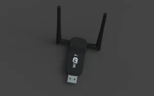
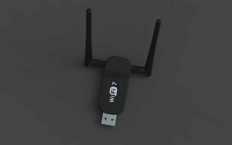
A USB adapter can be a practical choice for a gateway, industrial PC, service tool, or prototype where the host supports USB and board area is less constrained. It is normally a different product class from an embedded module, so assess its mechanical envelope, power demand, antenna position, and operating-system support separately.
PCB and Antenna Validation
Standard FR-4 is commonly viable for many 2.4 GHz and 5 GHz designs when the approved stack-up and reference layout are followed. For compact 6 GHz designs, demanding loss budgets, or non-standard stack-ups, obtain RF guidance and validate the finished board. Do not apply millimeter-wave design requirements to ordinary Wi-Fi designs unless the product actually uses a separate millimeter-wave radio.
Five Technical Selection Checks
1. Wireless Capability and Network Fit
Start with the application rather than the highest advertised throughput. Record the required Wi-Fi generation, 2.4/5/6 GHz bands, channel width, target region, transmit power, receiver sensitivity, and realistic range through the intended enclosure.
Also confirm station/AP modes, maximum client count where relevant, roaming behavior, IPv4/IPv6 needs, WPA2/WPA3 or enterprise-security requirements, and OTA-update support. A device that connects in a quiet lab may still fail in a dense deployment with co-channel interference.
2. Host, Clock, and Software Integration
Confirm the host interface—such as SDIO, SPI, UART, USB, or PCIe—along with voltage domains, reset behavior, boot timing, external crystal requirements, and GPIO availability. Check driver maturity for the target operating system or MCU SDK before design freeze.
Prefer a supplier with maintained firmware, documented errata, a security-update policy, reference designs, and a realistic product-support window. Capture these points in the approved-vendor list, not only in an engineer’s evaluation notes.
3. Power, Thermal, and Environmental Limits
Compare sleep, receive, and transmit values under equivalent settings. Review peak current, power-save behavior, operating-temperature range, storage conditions, and the thermal impact of sustained traffic. For outdoor or industrial equipment, temperature and enclosure effects can matter more than a small nominal current difference.
4. RF Layout and Test Access
Use the manufacturer’s reference layout for ground, impedance-controlled RF routing, decoupling, and antenna keep-out. Add a documented RF test point or connector only when it is appropriate for the validation plan; unused connector pads and stubs can degrade RF performance.
Validate output power, receiver sensitivity, spurious emissions, and antenna behavior on the final PCB in the final enclosure. Test across intended channels, orientations, supply conditions, and traffic loads.
5. Security and Product Maintenance
Wi-Fi selection affects the product’s security lifecycle. Confirm secure boot or signed-firmware options where relevant, credential-storage approach, supported TLS libraries, vulnerability-notification process, and the owner of OTA maintenance after launch. A part without a sustainable firmware path can become a sourcing risk even when silicon remains available.
Supply Continuity and Traceability
Technical fit is only half of component selection. Before approving a Wi-Fi IC or module, request the following for the exact manufacturer part number (MPN):

| RFQ item | Why it matters |
|---|---|
| Manufacturer, full MPN, and hardware/firmware revision | Prevents quoting a near-match or an unqualified revision |
| Price tiers, MOQ, SPQ, and NCNR terms | Establishes the true landed cost and purchasing commitment |
| Current lead time, allocation status, and capacity outlook | Identifies schedule risk before the production ramp |
| PCN, NRND, and EOL policy | Supports lifecycle planning and last-time-buy decisions |
| Authorized-channel status and chain-of-custody records | Reduces counterfeit and gray-market risk |
| Date code, lot traceability, CoC, and quality records | Supports incoming inspection and customer quality requirements |
| Approved alternates and revalidation plan | Reduces dependency on one source without assuming drop-in compatibility |
Sample parts should be tested from the same approved source and packaging condition planned for production. Keep the MPN, lot information, data-sheet revision, test results, PCB revision, and firmware version together in the qualification record.
Module vs. Chipset: Which to Choose?
Choose between a module and a bare chipset based on engineering resources, production volume, physical design, cost targets, and the required launch date.
| Decision factor | Wi-Fi module | Bare Wi-Fi chipset |
|---|---|---|
| RF integration | RF network and, often, antenna are supplied as a tested assembly | Product team owns layout, matching, antenna tuning, and RF validation |
| Development speed | Faster when the documented reference design is followed | Slower; requires more design iterations and test capability |
| Certification path | May simplify work in its approved configuration | Product team owns the full radio implementation and validation burden |
| Unit cost and area | Often higher cost and larger footprint | Can be optimized at scale, but NRE and validation cost are higher |
| Customization | Limited to the module’s interfaces and approved antenna options | Greater control of antenna, interfaces, board area, and system integration |
When a Module Is the Better Choice
Choose a module when launch speed, predictable RF integration, or limited in-house RF resources outweigh the higher unit cost. Verify its documented antenna options, software support, operating-temperature range, and approval conditions before committing to the PCB.
When a Chipset Is the Better Choice
Choose a bare chipset when the forecast volume and product constraints justify custom RF work. Budget for antenna matching, lab time, firmware work, pre-compliance testing, and the possibility of a board revision. A chipset is not a drop-in cost reduction unless the engineering and validation costs are included in the comparison.
How to Verify Wi-Fi IC Compliance
Compliance is determined by the finished device, its radio configuration, enclosure, ports, power supply, and target market. Start by identifying the regional route—for example, FCC equipment authorization in the United States and Radio Equipment Directive requirements in the European Union—then confirm the applicable standards with a qualified lab or compliance specialist.
EMC, ESD, and Surge: Keep the Roles Separate
- EMC work addresses emissions and immunity at the product level. Review grounding, return paths, power filtering, enclosure effects, and the actual test plan.
- ESD, EFT, and surge are separate immunity considerations with different exposure points and test levels. Apply protection where the interface and risk analysis require it.
- Use low-capacitance protection devices on exposed high-speed or RF-adjacent interfaces only when suitable for that interface. Do not place unsuitable protection on the antenna feed or assume a TVS improves radio compliance.
- Schottky and Zener diodes may serve power-path or clamping functions. They are not substitutes for a designed EMI filter.
RF Validation on the Finished PCB
Measure output power, receiver sensitivity, spurious emissions, harmonics, and antenna behavior on the final PCB in the final enclosure. Test across intended channels, orientations, supply conditions, and traffic loads. Controlled traces, impedance matching, connector pads, vias, and protection devices can all shift performance from the reference board.
During pre-compliance work, record radiated and conducted emissions, radio performance, failures, PCB revision, and firmware version. Correct the design before formal testing; do not rely on a component-level result to represent the final product.
Documents and Standards to Maintain
Keep the exact manufacturer data sheet, hardware design guide, antenna approval list, release notes, PCN/EOL notices, and module approval documents with the qualification record. Depending on the market, the review may include FCC Part 15, ETSI EN 300 328 or EN 301 893, EN 301 489, and IEC 61000-4-2 or IEC 61000-4-5. Confirm the current edition and applicability with the test laboratory.
Regulations, firmware, and lifecycle status change. Recheck these sources before design freeze, production release, and significant product revisions.
Sources and Further Reading
- Wi-Fi Alliance specifications overview for Wi-Fi technology terminology.
- FCC equipment authorization guidance for United States approval context.
- European Commission Radio Equipment Directive overview for European Union requirements.
- The exact manufacturer data sheet, hardware design guide, antenna approval list, release notes, PCN/EOL notices, and module approval documents for the selected MPN.
FAQ
Is a pre-certified Wi-Fi module always the best choice?
No. It is often the lowest-risk option for a fast launch or a team without RF resources, but it can cost more and occupy more board area. A bare chipset may be better at high volume if the design team can own RF development, validation, and lifecycle management.
What is the most important power specification for a battery IoT device?
There is no single number. Model the complete operating profile, including sleep, association, receive, transmit, retries, and regulator losses under the actual network settings.
What should a supplier quote include?
Request the full MPN, revision, MOQ/SPQ, price tiers, lead time, allocation status, authorized-channel confirmation, lifecycle status, PCN/EOL policy, date-code and lot traceability, and any approved alternates.
Conclusion
The right Wi-Fi IC is the part that meets the application’s radio, power, firmware, compliance, and supply-continuity requirements together. Build a shortlist from measurable operating conditions and MPN-level sourcing evidence, then validate the selected design in the final hardware.
Need a production-focused shortlist? Send Auxicen Electronics your target Wi-Fi bands, host interface, annual volume, operating temperature, and certification markets for an MPN comparison and lifecycle check.
Wi-Fi IC
wi-fi-ic
wifi-ic-sourcing-selection-guide-for-iot-devices
Wi-Fi IC Sourcing & Selection Guide for IoT Devices
SEO Description
Source Wi-Fi ICs for IoT with confidence: compare power, RF, antenna, module vs. chipset, certification, MOQ, lead time, lifecycle, and traceability.
A low unit price can be offset by RF redesign work, battery-life shortfalls, certification delays, or an unexpected lifecycle change. For IoT teams, unit price is only one part of the total BOM and production-cost decision.
This guide helps engineering and procurement teams build a production-ready Wi-Fi IC shortlist. Compare radio performance, power, integration effort, supply continuity, and final-product validation for 2.4 GHz, 5 GHz, or 6 GHz designs.
Key takeaways
- Estimate battery demand from current and time in every operating state—not from peak transmit current alone.
- Choose a module when time-to-market and RF risk matter most; choose a bare chipset when volume and design control justify the additional engineering.
- Compare Wi-Fi generation, bands, security, host interface, antenna constraints, and software support before requesting quotes.
- Put MOQ, lead time, lifecycle, PCN/EOL handling, authorization, and lot traceability into the same scorecard as electrical specifications.
- Treat a module approval as conditional. The final product, antenna, enclosure, and target market still determine the required compliance work.
Compare the Complete Wi-Fi Power Profile
Do not select a Wi-Fi IC from a single “low power” or peak-current claim. Battery life is driven by the current in sleep, association, receive, transmit, and processor-active states, plus the time spent in each state. Beacon intervals, DTIM settings, retry rate, transmit power, payload size, and temperature can all change the result.
Use this approximation when the supply voltage is constant:
average current = Σ(current in each state × time share of that state)
If rails differ, calculate energy instead: Σ(current × voltage × time).
Example Power-Profile Calculation
The table below is an illustrative calculation, not a measurement or a universal Wi-Fi IC specification. It assumes a 100-hour operating window at one supply voltage.
| Operating state | Example current (mA) | Time share | Energy over 100 h (mAh) | Relative energy share |
|---|---|---|---|---|
| Sleep | 0.02 | 90% | 1.8 | 0.5% |
| Standby | 8 | 5% | 40.0 | 10.6% |
| Receive | 55 | 3% | 165.0 | 43.8% |
| Transmit | 85 | 2% | 170.0 | 45.1% |
| Total / average | 3.768 mA average | 100% | 376.8 | 100% |
The calculation shows why short receive and transmit intervals can dominate energy use even when a device sleeps for most of the day. For every candidate, record the test voltage, PHY rate, bandwidth, transmit-power setting, association state, traffic pattern, and ambient temperature. Then confirm the result on production-like hardware.
Power-Supply Checks
- Size the regulator and local bulk capacitance for the radio’s documented transmit burst, not only its average current.
- Compare regulator efficiency at both burst load and low-load sleep conditions, including quiescent current.
- Place decoupling capacitors close to the vendor-recommended supply pins and follow the reference layout.
- Measure rail droop and temperature during sustained traffic. Supply instability can create retries and reduce real-world battery life.
Antenna and Integration Options
An embedded Wi-Fi module contains a radio chipset, RF matching network, and often an antenna. A bare chipset leaves those RF decisions to the product team. Choose the integration path based on schedule, annual volume, board area, and access to RF engineering and test resources.
Embedded Module with PCB-Trace Antenna
A surface-mount module with an integrated PCB-trace antenna can reduce RF design work and shorten integration time. Follow the supplier’s required ground clearance, keep-out zone, and board-edge placement exactly. Keep metal, batteries, displays, cables, and high-speed traces away from the antenna area.
The module’s regulatory approval applies only to its documented antenna and installation conditions. Confirm the approval documents before assuming they apply to the finished product.
Embedded Module with Chip Antenna
Chip-antenna modules can suit compact products, but antenna performance still depends on the host ground plane, clearance, enclosure material, and nearby components. Validate range, sensitivity, and emissions after the module is installed in the final enclosure.
USB Wi-Fi Adapter
A USB adapter can be a practical choice for a gateway, industrial PC, service tool, or prototype where the host supports USB and board area is less constrained. It is normally a different product class from an embedded module, so assess its mechanical envelope, power demand, antenna position, and operating-system support separately.
PCB and Antenna Validation
Standard FR-4 is commonly viable for many 2.4 GHz and 5 GHz designs when the approved stack-up and reference layout are followed. For compact 6 GHz designs, demanding loss budgets, or non-standard stack-ups, obtain RF guidance and validate the finished board. Do not apply millimeter-wave design requirements to ordinary Wi-Fi designs unless the product actually uses a separate millimeter-wave radio.
Five Technical Selection Checks
1. Wireless Capability and Network Fit
Start with the application rather than the highest advertised throughput. Record the required Wi-Fi generation, 2.4/5/6 GHz bands, channel width, target region, transmit power, receiver sensitivity, and realistic range through the intended enclosure.
Also confirm station/AP modes, maximum client count where relevant, roaming behavior, IPv4/IPv6 needs, WPA2/WPA3 or enterprise-security requirements, and OTA-update support. A device that connects in a quiet lab may still fail in a dense deployment with co-channel interference.
2. Host, Clock, and Software Integration
Confirm the host interface—such as SDIO, SPI, UART, USB, or PCIe—along with voltage domains, reset behavior, boot timing, external crystal requirements, and GPIO availability. Check driver maturity for the target operating system or MCU SDK before design freeze.
Prefer a supplier with maintained firmware, documented errata, a security-update policy, reference designs, and a realistic product-support window. Capture these points in the approved-vendor list, not only in an engineer’s evaluation notes.
3. Power, Thermal, and Environmental Limits
Compare sleep, receive, and transmit values under equivalent settings. Review peak current, power-save behavior, operating-temperature range, storage conditions, and the thermal impact of sustained traffic. For outdoor or industrial equipment, temperature and enclosure effects can matter more than a small nominal current difference.
4. RF Layout and Test Access
Use the manufacturer’s reference layout for ground, impedance-controlled RF routing, decoupling, and antenna keep-out. Add a documented RF test point or connector only when it is appropriate for the validation plan; unused connector pads and stubs can degrade RF performance.
Validate output power, receiver sensitivity, spurious emissions, and antenna behavior on the final PCB in the final enclosure. Test across intended channels, orientations, supply conditions, and traffic loads.
5. Security and Product Maintenance
Wi-Fi selection affects the product’s security lifecycle. Confirm secure boot or signed-firmware options where relevant, credential-storage approach, supported TLS libraries, vulnerability-notification process, and the owner of OTA maintenance after launch. A part without a sustainable firmware path can become a sourcing risk even when silicon remains available.
Supply Continuity and Traceability
Technical fit is only half of component selection. Before approving a Wi-Fi IC or module, request the following for the exact manufacturer part number (MPN):
| RFQ item | Why it matters |
|---|---|
| Manufacturer, full MPN, and hardware/firmware revision | Prevents quoting a near-match or an unqualified revision |
| Price tiers, MOQ, SPQ, and NCNR terms | Establishes the true landed cost and purchasing commitment |
| Current lead time, allocation status, and capacity outlook | Identifies schedule risk before the production ramp |
| PCN, NRND, and EOL policy | Supports lifecycle planning and last-time-buy decisions |
| Authorized-channel status and chain-of-custody records | Reduces counterfeit and gray-market risk |
| Date code, lot traceability, CoC, and quality records | Supports incoming inspection and customer quality requirements |
| Approved alternates and revalidation plan | Reduces dependency on one source without assuming drop-in compatibility |
Sample parts should be tested from the same approved source and packaging condition planned for production. Keep the MPN, lot information, data-sheet revision, test results, PCB revision, and firmware version together in the qualification record.
Module vs. Chipset: Which to Choose?
Choose between a module and a bare chipset based on engineering resources, production volume, physical design, cost targets, and the required launch date.
| Decision factor | Wi-Fi module | Bare Wi-Fi chipset |
|---|---|---|
| RF integration | RF network and, often, antenna are supplied as a tested assembly | Product team owns layout, matching, antenna tuning, and RF validation |
| Development speed | Faster when the documented reference design is followed | Slower; requires more design iterations and test capability |
| Certification path | May simplify work in its approved configuration | Product team owns the full radio implementation and validation burden |
| Unit cost and area | Often higher cost and larger footprint | Can be optimized at scale, but NRE and validation cost are higher |
| Customization | Limited to the module’s interfaces and approved antenna options | Greater control of antenna, interfaces, board area, and system integration |
When a Module Is the Better Choice
Choose a module when launch speed, predictable RF integration, or limited in-house RF resources outweigh the higher unit cost. Verify its documented antenna options, software support, operating-temperature range, and approval conditions before committing to the PCB.
When a Chipset Is the Better Choice
Choose a bare chipset when the forecast volume and product constraints justify custom RF work. Budget for antenna matching, lab time, firmware work, pre-compliance testing, and the possibility of a board revision. A chipset is not a drop-in cost reduction unless the engineering and validation costs are included in the comparison.
How to Verify Wi-Fi IC Compliance
Compliance is determined by the finished device, its radio configuration, enclosure, ports, power supply, and target market. Start by identifying the regional route—for example, FCC equipment authorization in the United States and Radio Equipment Directive requirements in the European Union—then confirm the applicable standards with a qualified lab or compliance specialist.
EMC, ESD, and Surge: Keep the Roles Separate
- EMC work addresses emissions and immunity at the product level. Review grounding, return paths, power filtering, enclosure effects, and the actual test plan.
- ESD, EFT, and surge are separate immunity considerations with different exposure points and test levels. Apply protection where the interface and risk analysis require it.
- Use low-capacitance protection devices on exposed high-speed or RF-adjacent interfaces only when suitable for that interface. Do not place unsuitable protection on the antenna feed or assume a TVS improves radio compliance.
- Schottky and Zener diodes may serve power-path or clamping functions. They are not substitutes for a designed EMI filter.
RF Validation on the Finished PCB
Measure output power, receiver sensitivity, spurious emissions, harmonics, and antenna behavior on the final PCB in the final enclosure. Test across intended channels, orientations, supply conditions, and traffic loads. Controlled traces, impedance matching, connector pads, vias, and protection devices can all shift performance from the reference board.
During pre-compliance work, record radiated and conducted emissions, radio performance, failures, PCB revision, and firmware version. Correct the design before formal testing; do not rely on a component-level result to represent the final product.
Documents and Standards to Maintain
Keep the exact manufacturer data sheet, hardware design guide, antenna approval list, release notes, PCN/EOL notices, and module approval documents with the qualification record. Depending on the market, the review may include FCC Part 15, ETSI EN 300 328 or EN 301 893, EN 301 489, and IEC 61000-4-2 or IEC 61000-4-5. Confirm the current edition and applicability with the test laboratory.
Regulations, firmware, and lifecycle status change. Recheck these sources before design freeze, production release, and significant product revisions.
Sources and Further Reading
- Wi-Fi Alliance specifications overview for Wi-Fi technology terminology.
- FCC equipment authorization guidance for United States approval context.
- European Commission Radio Equipment Directive overview for European Union requirements.
- The exact manufacturer data sheet, hardware design guide, antenna approval list, release notes, PCN/EOL notices, and module approval documents for the selected MPN.
FAQ
Is a pre-certified Wi-Fi module always the best choice?
No. It is often the lowest-risk option for a fast launch or a team without RF resources, but it can cost more and occupy more board area. A bare chipset may be better at high volume if the design team can own RF development, validation, and lifecycle management.
What is the most important power specification for a battery IoT device?
There is no single number. Model the complete operating profile, including sleep, association, receive, transmit, retries, and regulator losses under the actual network settings.
What should a supplier quote include?
Request the full MPN, revision, MOQ/SPQ, price tiers, lead time, allocation status, authorized-channel confirmation, lifecycle status, PCN/EOL policy, date-code and lot traceability, and any approved alternates.
Conclusion
The right Wi-Fi IC is the part that meets the application’s radio, power, firmware, compliance, and supply-continuity requirements together. Build a shortlist from measurable operating conditions and MPN-level sourcing evidence, then validate the selected design in the final hardware.