
Selecting a memory IC is a system decision, not a capacity-only purchase. The interface, voltage, organization, firmware behavior, package and lifecycle all have to match the host design. A part that looks similar in a distributor search can still fail boot, timing, endurance or traceability checks.
This guide follows the same order used in a real sourcing project: Serial EEPROM → NOR Flash → NAND / eMMC / UFS → DRAM / LPDDR → procurement RFQ and validation. It is written for hardware engineers, contract manufacturers and B2B buyers who need a qualified, repeatable supply rather than a one-off spot quote.
Memory IC technology at a glance
| Technology | Data retained without power | Typical host interface | Main sourcing question |
|---|---|---|---|
| Serial EEPROM | Yes | I²C, SPI or Microwire | Is the density, write endurance and address map compatible? |
| NOR Flash | Yes | SPI/QSPI/OSPI or parallel | Can the controller boot and execute from this device? |
| Raw NAND | Yes | ONFI or vendor-specific NAND bus | Who owns ECC, bad-block management and wear leveling? |
| eMMC / UFS | Yes | eMMC bus or M-PHY/UniPro | Are the embedded controller firmware and host protocol qualified? |
| DDR4/DDR5 DRAM | No | DDR memory interface | Do timing, rank, training and power rails match the controller? |
| LPDDR4/4X/5/5X | No | Low-power DDR interface | Does the SoC support the exact generation, package and topology? |
Capacity labels also need care: 8 Gb is one gigabyte of raw bits; 8 GB is eight gigabytes. Never use “32 GB lot” or “64 GB lot” as a substitute for the exact IC density and purchase quantity.
1. Serial EEPROM: small non-volatile data that must be dependable
Serial EEPROM is a good fit for calibration constants, configuration, board identity, user settings and other relatively small data sets. Microchip’s Serial EEPROM overview groups devices by I²C, SPI and Microwire interfaces; those interfaces are not pin-compatible by default.
RFQ fields for Serial EEPROM
- Exact MPN and ordering suffix: include the full temperature, package and tape-and-reel suffix.
- Interface and address map: I²C (including 7-bit address), SPI mode/maximum clock or Microwire; list address-pin states.
- Density and organization: for example, 2 Kb × 8 or 64 Kb × 8. Confirm page size and sequential-read behavior.
- Electrical limits: operating voltage, VIH/VIL thresholds, maximum clock, standby/write current and power-up behavior.
- Write behavior: page-write size, write-cycle time, ACK polling requirements, endurance and data-retention rating.
- Protection and qualification: hardware/software write protection, temperature grade, automotive grade where applicable, and lifecycle status.
The most common integration error is treating page-write size as a buffer size. If firmware crosses a page boundary, the address can wrap and overwrite earlier bytes. Validate the driver with the candidate’s datasheet, including power interruption during a write.
2. NOR Flash: boot code, firmware and execute-in-place
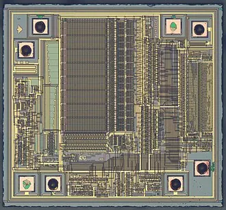
NOR Flash is commonly selected for boot firmware because it offers random reads and predictable address access. Modern serial NOR families use SPI, QSPI or OSPI with x1/x2/x4/x8 data lanes. “SPI Flash” is therefore a family description, not a complete specification.
NOR Flash selection checklist
- Boot and controller compatibility: verify JEDEC ID, reset sequence, 3-byte versus 4-byte addressing, dummy cycles, continuous-read mode and the host controller’s maximum frequency.
- Read topology: confirm whether the SoC supports x1, x4 or x8 (OSPI) at boot, and whether execute-in-place (XIP) is required. A device that reads quickly after initialization may still fail the ROM boot sequence.
- Erase geometry: record sector, subsector and block sizes, typical and maximum erase times, and whether protected regions are needed for boot images.
- Reliability: compare program/erase endurance, data retention over temperature, ECC features (if any), and supply-voltage behavior during brownout.
- Mechanical fit: match package, ball/lead pitch, thermal limits and PCB land pattern; confirm whether the assembly line can inspect and rework the package.
Keep a second-source list at the interface-command level, not only at the density level. Different vendors can use different status-register bits, quad-enable procedures or suspend/resume commands even when the package appears identical.
3. NAND / eMMC / UFS: separate the array from the controller
Micron’s NAND selection guide distinguishes NAND Flash, managed NAND, e.MMC and UFS. This distinction is essential in an RFQ.
Raw NAND versus managed NAND
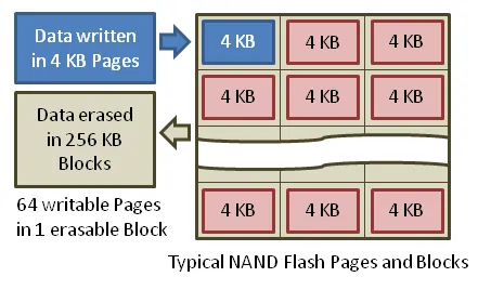
- Raw NAND exposes the flash array. The host or a companion controller must provide ECC, bad-block management, wear leveling, garbage collection and power-loss handling. ONFI compatibility alone does not guarantee firmware compatibility.
- eMMC combines NAND and a controller in one package and presents a standardized managed-storage interface. Confirm eMMC revision, boot partitions, RPMB needs, enhanced user data area, cache behavior and firmware revision.
- UFS is also managed storage, but its host stack is different: UFS uses M-PHY physical signaling and UniPro transport rather than the eMMC bus. Check UFS version, gear/lane support, boot LUN configuration, power modes and the SoC’s UFS controller.
| RFQ item | Raw NAND | eMMC | UFS |
|---|---|---|---|
| Controller supplied in package | No | Yes | Yes |
| Host integration burden | High | Medium | Medium/high |
| Key firmware dependency | ECC/FTL in host | Device firmware and eMMC protocol | Device firmware, UniPro/M-PHY and UFS protocol |
| Typical verification | Bad blocks, ECC margin, retention, power loss | Boot/RPMB, HS modes, endurance and power-fail tests | Link training, gears, LUNs, HS modes and power-fail tests |
For all three, specify usable capacity versus raw capacity, SLC/TLC mode where applicable, endurance or TBW target, data-retention temperature, package type, date-code limits and lot traceability. Do not present eMMC or UFS as drop-in replacements for an SPI NOR device; the PCB, boot ROM, driver and file-system assumptions are different.
4. DRAM / LPDDR: qualify the memory controller and the memory together
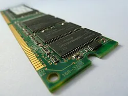
DRAM is volatile working memory, so it cannot replace Flash or EEPROM for retained data. DDR4 and DDR5 use a conventional DIMM or discrete-device topology; LPDDR4/4X/5/5X is optimized for lower power and is often soldered close to the SoC or integrated in a PoP package. LPDDR is not a pin-for-pin substitute for DDR.
What to put in a DRAM or LPDDR RFQ
- Generation and speed grade: specify DDR4/DDR5 or LPDDR4/4X/5/5X and quote data rate in MT/s, not only clock frequency.
- Organization: x8/x16 devices, channel width, rank count, bank groups, density per die and total system capacity.
- Timing: list the controller’s supported tCL/tRCD/tRP/tRAS ranges, training requirements and required SPD or firmware parameters.
- Power: VDD/VDDQ, VPP where relevant, low-power modes, refresh current and startup sequencing.
- Package and layout: BGA/PoP outline, ball map, escape routing, stack height, thermal limits and assembly profile.
- Lifecycle and qualification: commercial/industrial/automotive temperature range, process revision, PCN/PDN policy and sample availability.
Validation must include cold/warm boot, memory training, margin tests across voltage and temperature, refresh behavior, suspend/resume and long-duration data-pattern tests. A higher headline MT/s is not an improvement if the SoC, PCB topology or firmware cannot train it.
5. Procurement RFQ and validation workflow
Build an MPN-level RFQ
Send suppliers a controlled table rather than a product-family name. At minimum include:
| Field | Required detail |
|---|---|
| Identity | Exact MPN, manufacturer, ordering suffix, datasheet revision |
| Technical fit | Memory type, density/organization, interface, speed grade, voltage, temperature grade |
| Mechanical fit | Package, pitch, moisture sensitivity level, packing and reel quantity |
| Quality and compliance | Lifecycle status, PCN/PDN, date-code window, lot traceability, CoC, RoHS/REACH declarations; AEC-Q100 only when the automotive program requires it |
| Commercial terms | Authorized channel, MOQ, lead time, price basis, NCNR terms, allocation policy and sample quantity |
| Configuration | Programming or pre-programming image, key provisioning, boot partitions, RPMB or security requirements |
| Alternatives | Approved alternate MPNs, change-control owner and requalification trigger |
This separation prevents common category errors: ISO 9001 is a supplier quality-management certification; RoHS/REACH are regulatory material requirements; AEC-Q100 is an automotive IC qualification framework; and IPC-A-610 defines assembly acceptability. They support different decisions and should not be listed as interchangeable certificates.
Verify samples before committing production
- Document check: compare the quoted suffix, datasheet revision, PCN/PDN history and manufacturer’s lifecycle statement.
- Authenticity and traceability: inspect date code, lot code, package markings, moisture barrier bag, CoC and authorized-distributor chain. Record photos and retain a reference sample.
- Electrical characterization: test voltage corners, interface modes, maximum clock/data rate, current, reset and power-up/down behavior.
- Functional and firmware test: boot the actual board, exercise page writes or erase geometry, run ECC/FTL/file-system tests, and verify DRAM training and suspend/resume.
- Reliability screen: run temperature cycling or burn-in appropriate to the program, retention/endurance tests, power interruption tests and solder/assembly inspection.
- Production release: freeze the approved MPN and revision, define approved alternates, set incoming-inspection sampling, and require written approval for any PCN, date-code change or die revision.
For supply continuity, map manufacturer, assembly site, authorized route, lead time and allocation risk separately from the buffer-stock decision. Capacity such as 32 GB or 64 GB describes a device or module; the purchase lot should be calculated from forecast, lead time, shelf life and carrying cost.
FAQ
Can I replace a NOR Flash with eMMC or UFS?
Usually not as a drop-in change. eMMC and UFS include managed controllers and use different host protocols, boot configuration and firmware stacks. Treat the change as a hardware, bootloader and qualification project.
Is a larger density always a better substitute?
No. Check address width, organization, erase geometry, timing, voltage, package, boot behavior and lifecycle. A larger device can require a different driver or PCB footprint.
When should an automotive buyer request AEC-Q100?
When the device is part of an automotive program whose qualification plan requires it. AEC-Q100 does not replace RoHS/REACH declarations, supplier quality controls or board-level assembly acceptance.
What evidence should accompany a spot quote?
Request the exact MPN and suffix, manufacturer, date-code range, lot traceability, CoC, photos of labels and packaging, channel authorization, datasheet revision, PCN/PDN policy, and written disclosure of refurbished, remarked or mixed-lot material.
Conclusion
The safest memory IC purchase starts with the host design and ends with a documented validation record. Qualify Serial EEPROM by write behavior, NOR by boot and command compatibility, NAND/eMMC/UFS by controller and endurance responsibilities, and DRAM/LPDDR by timing, training and power. Then place an MPN-level RFQ with traceability, compliance and lifecycle terms included.
For help matching a BOM to authorized supply, see our Memory IC product range, technical advisory service, quality assurance process or contact page.
Authoritative references
- Microchip Serial EEPROM products and getting-started guidance
- Micron NAND Flash selection guide
- Micron managed NAND, e.MMC and UFS overview
- Micron NOR Flash products
- JEDEC standards
- AEC-Q100 automotive IC qualification
- IPC-A-610 electronic assemblies acceptability
- European Commission RoHS directive and REACH regulation